Lab 4
Graphic Design Is My Passion
Introduction
In Lecture 5, we covered the basics behind how a VGA works as well as some practices to keep in mind when you’re working with your VGA. This lab will have you implement those practices in a way where you can use your code in your final capstone project. Today, you’ll learn how writing to the VGA works, implement ping-pong RAM, and for some extra credit, basic blocking to implement a static image.
Resources and Reference Material
Link to Lecture 5
Contact Us
You can contact the DAV leads on Discord.
Claire Huang (Discord: zhiyujia)
Premkumar Giridhar (Discord: 8bitrobot)
1 VGArbage
To get started, we’ve provided a skeleton for you.
You’ll observe that the gist of the VGA is mostly counters and some combinational logic. You keep track of where you currently are on the VGA using some counters in the sequential block (and some related localparams), and what actually displays on that part of the VGA is determined in the combinational block.
Your job now is to fill out the skeleton. We’ve labeled the four parts as TODO(1), TODO(2), TODO(3), TODO(4) for your reference. The actual tasks should be fairly straightforward (and they’re outlined in the skeleton!), but we’ll describe them in this lab spec as well for completeness.
1.1 The VGA Constants
Here, you’re presented with 8 constants that you need to find the values for. You can easily find these numbers by Googling “VGA timing spec” or similar. You can also find them in our lecture slides :-)
Just keep in mind what each one is conceptually – you’ll need them later!
1.2 The Pixel Counters
The pixel counters are the brain behind the VGA driver, and the sequential block triggered on the edge of our VGA clock is where we update them. If the reset button is pressed, you need to reset these counters to zero. Otherwise, you should increment the appropriate counter. The logic for counter increments is fairly straightforward – increment the horizontal counter hc, and if it gets too high, increment vc and set hc back to zero. You’ll need to use the parameters you defined earlier to figure out at what value of hc you need to move to the next line.
Also, keep in mind that hc and vc are zero-indexed when writing your conditions for incrementing them! If hc equals 800 at any point, you did something wrong :-)
1.3 hsync and vsync
Here, you’ll combinationally generate the hsync and vsync signals using the counter values. The parameters we defined earlier will come in handy here. Remember two things when figuring out the assignments:
hsyncandvsyncshould be HIGH for most of the time and driven LOW during the specific period within the blanking interval- the duration of
hsyncandvsyncis susceptible to off-by-one errors – make sure to double-check your conditions!
1.4 The Pixel Color
Finally, you’ll use a combinational block to assign the pixel color outputs red, green, and blue. Remember to assign all the colors to 0 during blanking intervals and resets – otherwise, just assign the color values inputted via input_red, input_green, and input_blue.
1.5 The Top Level
This isn’t labeled in the skeleton because you need to make it yourself, but in addition to filling out the VGA skeleton, you need a top level to drive it. This will include the following tasks:
- Creating and instantiating a 25 MHz clock using a PLL
- Instantiating the VGA module
- Pin planning!
It’ll be fairly obvious if your module is working as expected, so you probably don’t need to testbench for this one. But if you’re having weird timing issues and can’t figure out why, there’s nothing a testbench can’t help you figure out!
2 I Can’t Win
In this section, you’ll be implementing ping-pong RAM. If you recall from lecture, ping-pong RAM is a technique where our VGA reads from one memory buffer while our graphics driver writes to the other. This prevents the VGA from having its image change while it’s being read – a very common source of screen-tearing.
To implement this, it might be easier to first create the RAM as two arrays of registers, with one byte for each pixel on the screen (now you see why we used 8-bit color?). Once we have this working, we’ll replace the arrays with RAM IPs.
For this module, you should take in the following inputs:
- A clock, to allow synchronous changes of the read and write RAM,
- The address to write at, or
addrWrite. This is dependent on the size of your array. - Two values for
addrRead_handaddrRead_v, which can be taken from your VGA module (remember the countershcandvc?), - And the data to write, or
dataWrite. The size of this is dependent on the size of your colors - if your red, green, and blue pixels are 4 bits each, this will be 12 bits.
Your module should output whatever was at the read address.
Now for the actual ping pong part. To switch the two RAMs, you can instantiate a 1 bit writeEnable register. Then, when addrRead_h and addrRead_v both reach zero (a.k.a. the start of the frame), the writeEnable register can be flipped. Make sure that the flipping is done sequentially, to keep everything in sync. In the combinational block, the selection of which RAM buffer to read/write can be determined based on writeEnable, and this address can be used to read the data out to the VGA module. That means that this ping pong RAM module will need to be instantiated in the top level where you instantiated your VGA module.
Wow, that was a lot. What do you even do with this ping pong RAM?
3 Graphic Design Will Be Your Passion Too
To encourage best practices, you’ll implement a very basic graphics module too. Don’t worry, you can just hardcode this part for now. This is just to show you a structure you can use for your final capstone project.
This graphics module will also be implemented in the same top level as the other two modules. The gist of this module is that you supply it with an address and it tells you what color you need to put in your ping pong RAM, which will get sent to the VGA.
In the graphics module, you’ll want to take in the horizontal and vertical position (you can keep it as the HSYNC and VSYNC outputs from the VGA for now).
The module should output the following:
- The color to be sent to the ping pong RAM,
- And the address to read/write from in the ping pong RAM.
(All of this is combinational, so there’s no clock involved in this one!)
To calculate the address - if the horizontal and vertical position are in the blanking interval, set the address to 0. Otherwise, you can find the address by calculating vertical position * (number of pixels in a row) + horizontal position.
To calculate the color, you can just hard code it to return a certain color if it’s not in the blanking interval. If the horizontal and vertical positions are within the blanking interval, then the color should be all 0’s.
Now, it’s a matter of wiring up the inputs and outputs from the modules you created, and now you have a VGA using ping pong RAM!
? Extra credit
If you want to go above and beyond on this lab, here’s a little exercise that will introduce you to blocking.
Your job is to display this lad (shown below) on your VGA!
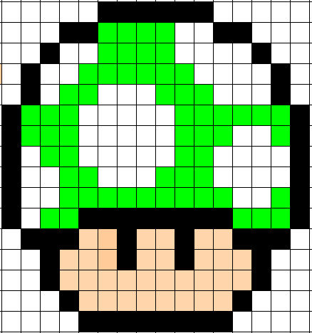
Remember that graphics module you created? You could in theory use the vertical position and horizontal position to specify a position within an array, and that array can be encoded with certain colors at each index. Then, you can just grab the color out of that array and pass it to the ping pong RAM, and everything will work like it did before.
However! If we continued just like that, this mushroom would be very, very small. Each square would only be one pixel! What if we want to make this larger?
Well, we can implement a technique called blocking! In the top level, you can assign some wires to be a smaller version of the horizontal position and vertical position.
// horizontal_position ranges from 0 to 799
// vertical_position ranges from 0 t0 525

// x ranges from 0 to 39  (image width is 32px)
assign x = horizontal_position / 20;
// y ranges from 0 to 26 (image height is 24px)
assign y = vertical_position / 20;
For the 16x16px image given above, your division factors will have to be slightly different.
Of course, this does mean that you will need to adjust your conditions in your graphics module to the new boundaries (where is the new blanking interval?). Once you’ve done that, though, you can use x and y as the address to your array or RAM and pull the color out that way. Then, everything else is the same as it was before!