Lab 3
6 FFT Under
- 0 Useful Diagrams
- 1 A Twiddle Bit Annoying
- 2 I can't belive it's not butter-fly
- 3 4ruit by the FFT
- 4 You're Fourgiven
- 5 Checkoff
Introduction
Ah yes, the FFT. In lecture 3, we covered how the Fast Fourier Transform (FFT) works conceptually and broke it down into parts, and now it’s your turn to make it! In this lab, you’ll be taking four inputs, designing butterfly units, and connecting them to form a 4-point FFT module. This is the basic building block to the final Digital Audio Visualizer capstone, where you’ll need to take audio signals and convert them to the frequency domain with a minimum of a 16-point FFT.
Resources and Reference Material
Contact Us
You can contact the DAV leads on Discord.
Claire Huang (Discord: zhiyujia)
Premkumar Giridhar (Discord: 8bitrobot)
0 Useful Diagrams
1 A Twiddle Bit Annoying
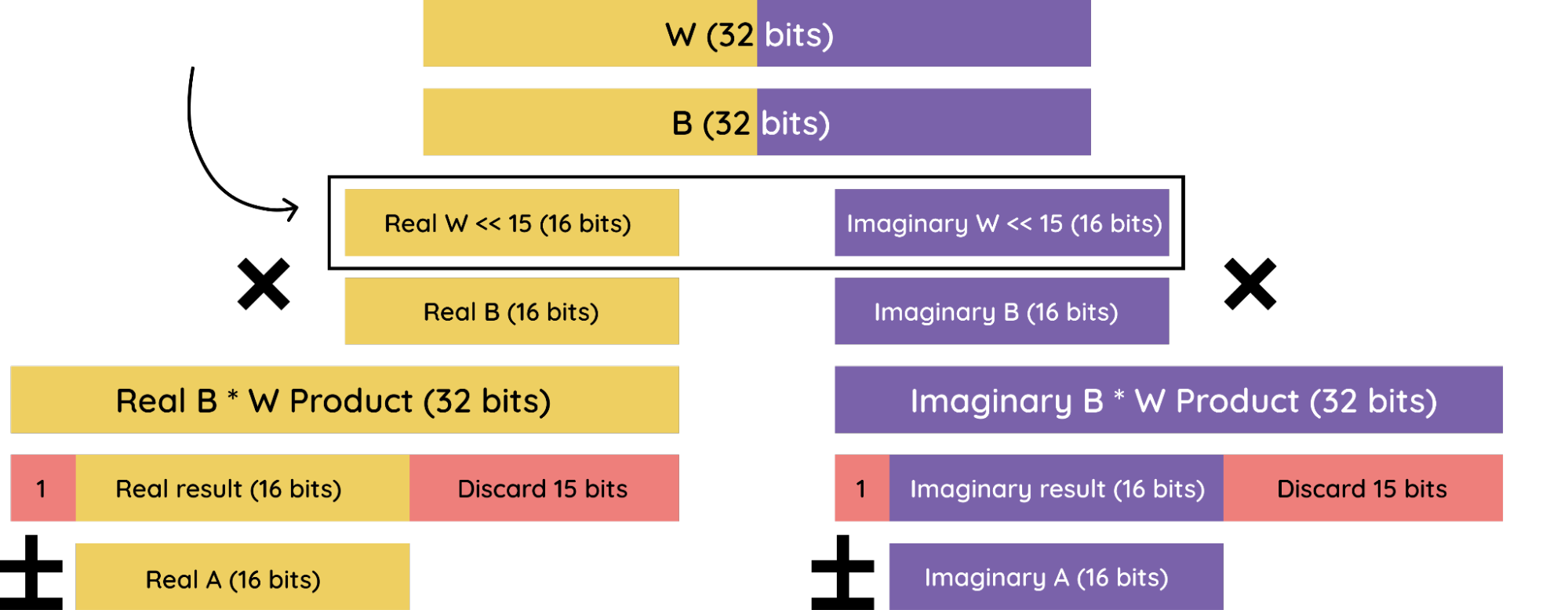
Let’s start out with our twiddle factors. In this lab, we’ll be working with inputs that are 32 bits each – 16 real and 16 imaginary. This means that our twiddle factor will also be 32 bits, with 16 real bits and 16 imaginary. Remember to keep everything in two’s complement form!
Recall what a twiddle factor is from Lecture 3:

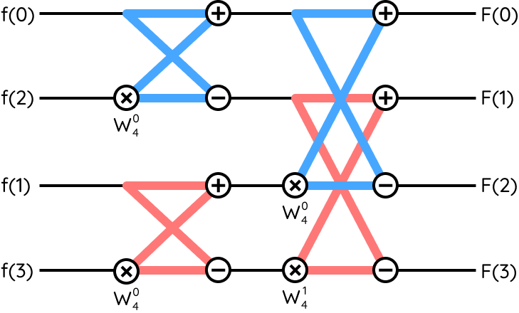
Also recall from lecture that we derive these twiddle factors by dividing up a unit circle. You’d usually expect four twiddle factors; but due to the symmetry of the unit circle, we can get away with just two (each one being positive/negative). That’s why in the 4-point FFT diagram above, there are only two twiddle factors (but their positions on the unit circle are the same as before!). You can use Euler’s, as shown in the equation above, to calculate these twiddle factors - the cosine part will be real, and the sine part will be imaginary.
In lecture, we also discussed that at the end of the multiplication process, we truncate by discarding the sign bit and taking the next 16 bits, discarding the last 15 at the end. Remember that this is essentially dividing the result by 215. In order to counter this operation and avoid losing magnitude in our numbers, remember to left-shift your twiddle factor by 15, or more simply multiply it by 215 prior to encoding it into your module.
In Verilog, floating point math is hard, but signed integer math is easy! This has the following implications on our module.
- Every single port and wire in the butterfly unit should be declared using the
signedkeyword. This will affect the automatic sign-extension and rounding/overflow behavior, so it’s very important that you remember to include it.
module (
    input signed [WIDTH-1:0] A
);
    wire signed [WIDTH-1:0] C = A;
endmodule
- Once you multiply your twiddle factor by 215, you need to round to the nearest 16-bit integer and use that value as the twiddle factor in your module.
- When your twiddle factor is 1, multiplying it by 215 will cause it to overflow, you should instead use the largest possible signed 16-bit value – 16’b0111 1111 1111 1111.
2 I can’t believe it’s not butter-fly
It’s time to build the basic building block of our Fast Fourier Transform! Recall from lecture that the butterfly unit looks like this:

2.1 The Ports
Your butterfly unit should have the following:
- A parameter named WIDTH that determines the number of bits in the inputs. Our inputs for this part are 32 bits (16 real and 16 imaginary), so give it a default value of 32.
- If you don't know what parameters are, please refer to the Verilog Docs section on the topic :)
- Three WIDTH sized inputs. These will be A, B, and W.
- Two WIDTH sized outputs. These will be (A+WB) and (A-WB).
As mentioned before, everything will be in the same format - the left WIDTH/2 bits will be real, and the right WIDTH/2 bits will be imaginary. It might help you to split these up into separate wires within the module for the real and imaginary component of each input, to make the math easier to follow around.
2.2 The Multiplication
When we’re multiplying two complex numbers, we can use the FOIL method.

Make sure to test your results using a testbench! We’ve added a Python script to help you out with this. In the script, you should be able to input Areal, Breal, Aimag, and Bimag, as well as 4 twiddle factors. You should test that your outputs match the script; you may find your results off by a small amount, but it’s okay as long as your outputs are really only off by a little bit. It helps to test your module with somewhat large values – say, ±100 or greater – because the math is more susceptible to these rounding errors when the numbers are smaller.
3 4ruit by the FFT
It’s time to make the 4-point FFT!
We want to build the FFT using a finite state machine. Our inputs will look a little bit different! Now, we have:
- Four 32-bit complex inputs representing the samples being FFT’d
- 1-bit clock, 1-bit reset inputs
- 1-bit start input
And now, we want to output:
- **Four ** 32-bit complex outputs
- 1-bit “done” output (indicating when the FFT computation is done)
So how do we make this a finite state machine? We can treat each vertical “layer” of butterfly units as a state, along with a “RESET” state and a “DONE” state. During each state of our module, the inputs to the butterfly units will be set as the outputs of the previous state. This also means that we can reuse our butterfly units, so you’ll only need enough butterfly unit instantiations to perform the computations for one state. The twiddle factors will be hardcoded into this module.
Since we’re doing a 4-point FFT, we only need log2(4) = 2 stages. Our finite state machine could look like this:
| State | Description |
|---|---|
| RESET | Outputs are held at 0 until the start input goes high. When it does, go to STAGE1. |
| STAGE1 | The butterfly units’ inputs are set as the inputs to the module. The outputs are then calculated combinatorially. After one clock cycle, go to STAGE2. |
| STAGE2 | The butterfly units’ outputs are used to update their own inputs – refer to the diagram for the correct wiring. After one clock cycle, go to DONE. |
| DONE | The outputs of the module are set to the results of STAGE2. The done flag is set high. Wait until the reset input goes high to return to RESET. |
Once you’re done, use our testbench to test your new 32-bit 4-point FFT! You can then check this with the Python script to verify that the outputs are correct.
4 You’re Fourgiven
Anyways, you’re almost done with this lab! Just one more thing to do.
We’re now going to transform our 32-bit FFT into a 16-bit FFT! This is useful because sometimes we want to use less precision to save space. This should be trivial if you parametrized everything earlier. Just change WIDTH to 16 (and make other changes to variable sizes as necessary). Remember, the twiddle factor only needs to be shifted by 7, and the truncation is also slightly different.
Make sure to test your design with a testbench!